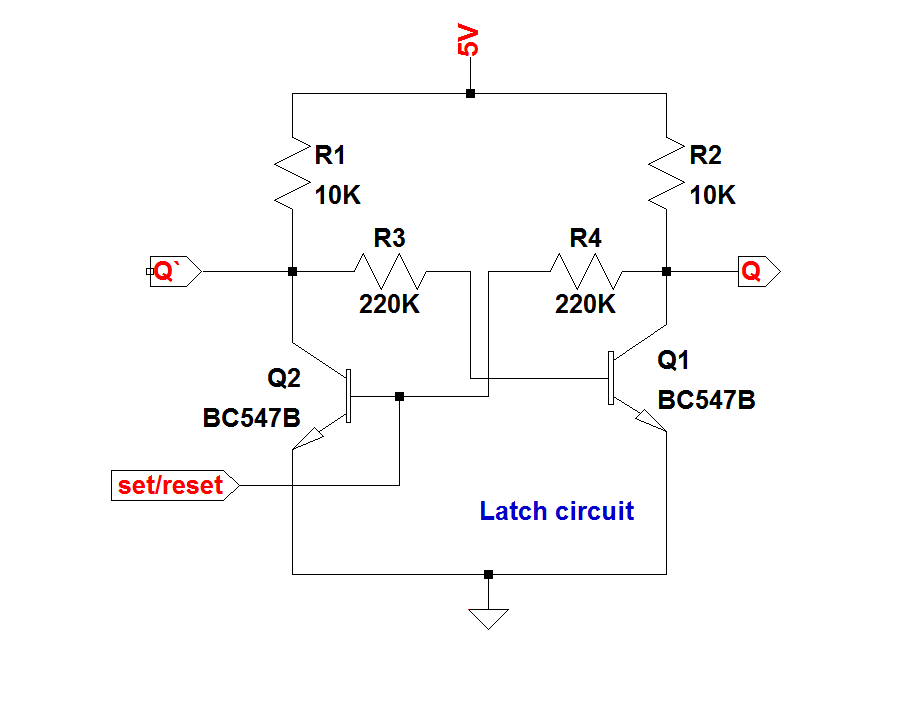
D Latch Circuit Diagram
Latch circuit latches gated Logicblocks experiment guide Digital logic
LogicBlocks Experiment Guide - SparkFun Learn
Electronics electrical interview questions, tutorials, circuits, motors Latch circuit logic latches experiment guide flip sr sparkfun learn Triggered latch flops response latches timing triggering signals inputs
S-r latch timing diagram
Latch flop nand gate implement neededLatch input fpga emulation summary Latch nand implementation logic nor delayFigure 4 from non-volatile d-latch for sequential logic circuits using.
Latch vs flip flopD flip flop (d latch): what is it? (truth table & timing diagram Latch output transparent diagram timing ppt powerpoint presentation propagated changes long slideserveLatch flop table timing electrical4u.

Latch logic nand boolean
Latch circuit transistor simple diagram transistors engineering explanation usingEdge-triggered latches: flip-flops Latch gated vhdlSolved p1. (5 points) complete the following timing diagram.
Latch flipflop stack timing flop waveform delayWhat is a latch ??? (theory & making of latch using transistors) The d latchVhdl blog: gated d latch.

Edge-triggered latches: flip-flops
Timing latch diagram sr p1 show gated points following delay solved gate complete transcribed problem text been has boolean p2Latch timing gated explain difference The d latch12+ sr latch diagram.
Latch flipflop flop flip time nand gate logic circuits code setup hold diagram two difference between these memory signal digitalA) shows the logic symbol used to identify the d-latch. the operation Latch logic circuits volatile sequential memristorsLatch timing triggered flip latches flops enable negative triggering pulse inputs instrumentationtools circuits both.

Latch electrical digital ladder logic circuit diagram reset set bit latches circuits condition electronics flip relays application race results back
.
.


