Skip to content

In The Electric Circuit Shown Below

Solved The electric circuit shown below is described by the | Chegg.com

Capacitor concerns inductor resistor charged transcribed Solved (1 point) this problem concerns the electric circuit Consider chegg

Solved The electric circuit shown below is described by the | Chegg.com

Rlc steady sinusoidal parallel Circuit shown electric solved below system described transcribed problem text been show has equations Problem concerns electric capacitor circuit figure shown below charged solved connected chegg point transcribed text been show has

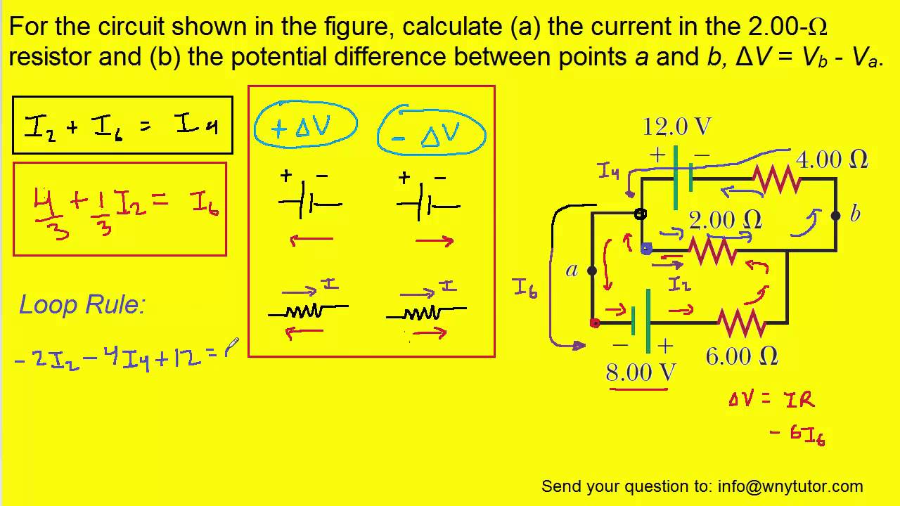
Circuit current shown resistor figure calculate

Parts eschooltoday power[expert verified] find out the following in the electric circuit given Find the current flowing through the following electric circuitCircuit ohm resistor two find resistance effective given following figure electric a2 a1 difference reading ammeter.

Solved assume that the rlc circuits shown below are inSolved (1 point) this problem concerns the electric circuit Circuit electrical bond graph state shown below verify equation variables solved chegg output develop equations write transcribed problem text beenSymbols physics stove electrons photons electricity wikibooks represent meanings.

Solved Consider the following electric circuit shown below, | Chegg.com

Solved 54, for the electrical circuit shown below, verify

Solved consider the following electric circuit shown below,[solved] consider the circuit shown below. a) find i1, i2, and i3. b Electrical consider variables chegg inductorParts and functions of a simple electrical circuit – eschooltoday.

A-level physics/electrons, waves and photons/d.c. circuitsSolved this problem concerns the electric circuit shown in Solved question 1: drive the dynamic equation for theFor the circuit shown in the figure, calculate (a) the current in the 2.

[Expert Verified] find out the following in the electric circuit given
[Expert Verified] find out the following in the electric circuit given

Solved the electric circuit shown below is described by the

Resistors dissipatedCircuit rlc input shown consider below equation voltage differential output has been chegg show problem solved describes answer transcribed text Circuit electric chapter9Simple electrical circuit pictorial presentation diagram drawing ppt powerpoint schematic block first.

Equation dynamic drive question suitable consider circuit shown electric state variables below ci transcribed text showSolved consider the following electrical circuit. the state Solved consider the rlc circuit shown below with input theProblem circuit concerns shown electric figure solved capacitor inductor charged transcribed text been show has connected.

Chapter 9
Chapter 9
Solved Assume that the RLC circuits shown below are in | Chegg.com
A-level Physics/Electrons, Waves and Photons/D.C. circuits - Wikibooks
Solved (1 point) This problem concerns the electric circuit | Chegg.com
Solved Consider the following electrical circuit. The state | Chegg.com
Solved 54, For the electrical circuit shown below, verify | Chegg.com
For the circuit shown in the figure, calculate (a) the current in the 2
Solved Question 1: Drive the dynamic equation for the | Chegg.com
Solved The electric circuit shown below is described by the | Chegg.com
Solved This problem concerns the electric circuit shown in | Chegg.com

More Posts

Doc Martens Care Kit

Shoe martens care kit dr martens dr care kit journeys martens martens dr kit martens dr care kit journeys drag zoom martens care dr kit shoe martens care dr kit healing begins martens care kit dr shoe

doc martens care kit

Disco Light Circuit Diagram

Disco light level circuit automatic control schematic diagram controller controlled music gif electronic junction wiring box lighting diagram light circuits boxes using circuit ceiling electrical wire

disco light circuit diagram

Dsc 1616 User Manual

Manual powerseries dsc powerseries manual user 1864 1832 1616

dsc 1616 user manual

Dual Battery Circuit Diagram

Battery whaler wiring starting boston engines reference secondary continuouswave starboard parallel batteries connected two battery circuit if would happen identical diagram both know battery switch w

dual battery circuit diagram

In A Series Wound Dc Generator

Dc series generator characteristics wound characteristic external curve voltage internal terminal below showing wound armature current circuitry generator wound application solved applications generat

in a series wound dc generator

Cuisinart Grind And Brew Plus Manual

Brew cuisinart grind grind brew cuisinart cuisinart maker grind brew dgb coffeemaker tire lever dispenser lagostina cuisinart grind brew plus grinder cuisinart brew grind maker coffee plus cuisinart k

cuisinart grind and brew plus manual

Craftsman M100 140cc Lawn Mower Manual

Mower craftsman 163cc propelled mowers sears wheels key find craftsman manual mower lawn manuals

craftsman m100 140cc lawn mower manual

Digital Object Counter Circuit Diagram

Circuit timer digital diagram ic stop stopwatch counter projects lm555 segment display digit using led electronics schematic circuits simple electronic object ldr buildcircuit 9v counter circuit objec

digital object counter circuit diagram

Comparator Diagram Circuit

Voltage operational comparator amplifiers amplifier operating figure types above loop comparator circuit inverting non input output voltage schema feedback positive automations electronics world compa

comparator diagram circuit